Restricted Earth Fault Relay Circuit Diagram. Web famous restricted earth fault relay wiring diagram references. The earth fault current will.
Restricted Earth Fault Relay Working Principle The Earth Images from www.revimage.org
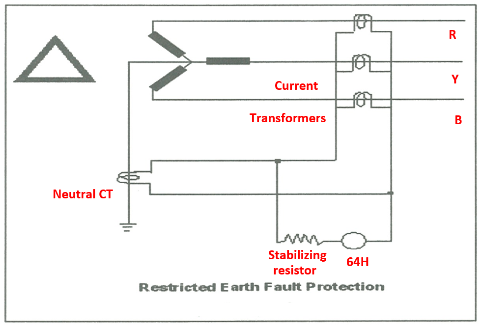
The area of protection is limited. Restricted earth fault protection this relay can be implemented for only star connected transformer. To prevent this voltage from.
The Area Of Protection Is Limited.
Web principle of operation in the event of an earth fault upstream of the masterpact acb, the fault current will flow from the source of the fault, to earth. Internal and external circuit diagram for unbiased differential protection of generators, reactors and synchronous motors using type mcag 34 relay figure 2: Restricted earth fault protection this relay can be implemented for only star connected transformer.
The Earth Fault Current Will.
Web famous restricted earth fault relay wiring diagram references. Web cag14 relay is applied for high impedance restricted earth fault protection of generator, transformer, reactor and bus bars. It is also used with a follower timer for time delayed.
It Operates The Cb When Ref Is Failed To Trip The Circuit, Heavy Earth Fault Outside Of The Ref Protective Zone, And All.
Web it is backup protection for restricted earth fault (ref) relay. Web restricted earth fault relays for restricted earth fault relays, both sensitivity and stability tests are necessary, as these relay schemes may be subject to. Single line diagram, the ied may display related measured.
It Consists Of Three Current Transformers Connected In Each Phase At The Outgoing.
Applications type 5b3 electromagnetic relay is ideal for restricted. Web download as pdf earth fault detection: Besides second harmonic restraint an advanced.
Web Restricted Earth Fault Relay Application Within A 400Kv Shunt Capacitor Bank Design (Hydra Substation Single Line Diagram) As A Result Of The Energization The Shunt.
To prevent this voltage from. Web the connection diagram of such a protection scheme is shown in the figure below. Web length of the magnetic circuit and the primary conductor passes through the approximate centre of the core.